


Tachometer Wiring

Legacy Blog Content!
You are viewing legacy content from The Art of Diesel’s blog site. Information and links may be outdated. Referenced video might no longer exist. Embedded photos might be missing. We are keeping this content available to our readers in case there might still be some valuable information contained.
******************************
On the Diesel Suburban project, I should provide a couple updates and show how I got the tachometer working.
Since the diesel was installed, I haven't driven the vehicle too much. I drove it to work for a few days to show off and check my mileage. I topped off the tank before the first day, drove it three days, topped it off again, and did the math. The verdict was that I was getting 22 mpg -- which isn't bad for mixed driving (EPA and Fuelly both show 1999 Suburbans as getting around 14 mpg in mixed driving). We live southwest of Indianapolis and visited some family north of Dayton, OH a couple weekends ago. I purposely topped it off before we hit the highway and checked the mileage when we were close to our destination. Highway mileage was 25 mpg -- which, again, isn't bad for punching a hole through the air at 70-75 mph with a large brick-shaped object. 17 mpg is what would be expected with the 5.7 liter V-8.
Driveability isn't bad, unless you really need to accelerate -- such as on a short, uphill highway ramp. The engine is still stock, other than backing out the power screw slightly. The stock Garrett turbo is the version without a wastegate, and is purposely designed so that it'll never spool up enough that one is needed. Under normal driving conditions, I might see 5 psi on the boost gauge and 12 psi if I'm trying for maximum acceleration and wind up the engine to about 3,000 rpm. In 5th gear at 70 mph, this engine is only turning 1900 rpm. I need more boost and torque available in the mid-range rpms, so I've ordered an upgraded turbo. I'll cover that in more detail when I begin installing it.
I knew what my rpms would be at any given speed by doing some math, knowing my tire diameter, rear end gear ratio, and the ratio of the gear I'm in. It's a pretty simple calculation, at least once the unit conversions are straight. In order to know what conditions I was exposing the engine to, I had already installed boost and pyro gauges. I wasn't able to actively monitor my rpms, though, until I installed a Dakota Digital DSL-1.
Because diesel engines don't have a coil to provide an ignition signal for the tachometer to measure, we are forced to find other ways to get a signal that's proportional to engine rpm. One way to get a signal would be to use the "P" connection on the 140-amp (CS144) alternator's "SFLP" plug. The "P" connection sees the oscillations of a single stator and provides a signal that can be used. The DSL-1 is essentially a frequency convertor that takes a signal at one frequency and either multiplies or divides that signal's frequency by the right ratio to emulate a V-8 signal.
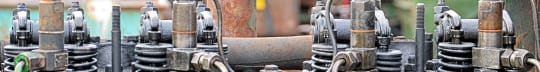
The sensor with the blue goop on it to the left of the timing opening was to be used to drive the tachometer
I considered using the alternator's connector, but thought it would be slick to use the sensor that was already on the 4BD1T. This sensor is on the engine's right side, mounted on the case in a position where it can measure the passing of injection pump gear teeth. It is positioned just aft of the injection timing access cover. I'm showing an old photo here, because I've mounted the air conditioning compressor over these items (it can be unbolted and moved out of the way when needed). I'm not sure how the NPR truck used this sensor (for a tach, perhaps?), but I was determined to use it for my tachometer.
When I was removing the 5.7 V-8 from the Suburban, I carefully marked a number of wires that I thought would come in handy later for the few engine sensors this diesel would have. I've previously discussed how I used the stock sensors from the V-8 to drive the temperature and oil pressure gauges in the Suburban.
This is the ignition connector that originally drove the Suburban's tach.
It's always best to use things in a way that's consistent with their original design--even if you are altering a machine's purpose to fit your will! So, while I was taking the engine out, I was consulting a combination of Mitchell 1's wiring diagrams and Rock Auto's connector photos. The white wire in this connector was believed to drive the tach. (Sorry about the photo quality, my camera died and I took this one with my phone's cheesy camera.)
Before I ran any wires through the firewall or did anything permanent, I tried this system out by running some jumper wires around in the engine compartment and hooking up the DSL-1 right there, feeding the device's output to the ignition connector.
The connections required to make the DSL-1 work are relatively simple. Naturally, the device requires power, so I fed it +12V and ground. The sensor I was using had two wires, and I didn't know which one should be "ground," so I tried it both ways. The DSL-1 saw and converted the signal both ways, so polarity wasn't an issue.
I played with a number of modes on the DSL-1, trying to get the right frequency conversion to get the tach fairly close. The flywheel tooth sensor mode was designed for flywheels that typically have over 100 teeth, so the tach would read way too low, even on the highest setting (this sensor will see 25 teeth for every revolution of the engine). I changed the device over to the alternator mode, and quickly found that the output was way too high, even on the lowest setting. I was thinking that if I could knock off a factor of two, everything would be OK. Staring at the manual, I noticed that in addition to the 8-cylinder output I was using there was a 4-cylinder output. Eureka! I moved the output to the 4-cylinder output, and found that the tach was in the right range for how fast the engine was idling.
The Tachometer Input is Identified Behind the Instrument Cluster
Then, I took all the jumpers off and started to install the DSL-1 for real. It isn't a sealed unit, or something that's ruggedized for the under-hood environment. It needs to be mounted inside the cab--preferably within reach of the driver. After pulling the dash bezel and removing the instrument cluster, I found a "shelf" just below the instrument cluster that would be a good place to attach the DSL-1. I marked that location. I took a close look at the connector behind the instrument cluster and unsnapped it from where it is held down. I found two white wires, so I did a continuity check and identified the correct wire. I then cut it and ran the DSL-1's 4-cylinder output to it. After identifying a good ground and switched power wire from nearby cables, I used them to power the device. I also ran two wires from the gear tooth sensor to this location and finished wiring the DSL-1.
The DSL-1 was mounted below the instrument cluster.
I pulled out my spreadsheet for rpms at speed in the different gears, and saw that the engine should be turning 2000 rpm at 55 mph. So, I took the Suburban for a drive without reinstalling the dash beze. I was able to use the UP and DOWN buttons on the DSL-1 to tune the tach. I held my speed 55 mph, adjusting it to read 2000 rpm. The speedometer's accuracy had previously been confirmed using GPS -- so I knew it would be accurate.
That all sounds really easy, doesn't it? Running the wires was painful, and I always get claustrophobic when working under the dash in a hot environment, but I'm quite happy with how this works!
--Putting the "engine" back in engineering!